| doc/img | ||
| PWM-to-DC | ||
| .gitignore | ||
| LICENSE | ||
| README.md | ||
pwm-fan-control
This is a simple circuit to allow using a DC fan (3 pins) on a motherboard supporting only PWM fans (4 pins).
This system does not allow variable fan spin, instead it will either turn it on (if there is any active PWM signal), or turn if off (if PWM is constantly zero).
Files on this repository are meant to be used with KiCad v8.x
Overview
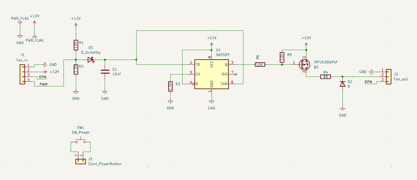
The voltage divider made by R1 and R2 act as a 3V pull-up for the PWM signal. This is because PWM output is open-collector.
When the PWM signal is high (open), capacitor C1 is charged through diode D1 (so a little less than 3V due to D1 voltage drop). When the PWM signal is low (connected to ground), the capacitor C1 remains charged because D1 blocks discharge. It will discharge itself over time, but slowly enough that for a 25kHz PWM signal it will remain permanently at almost fully charged. However, if the PWM signal remains constantly low (when the motherboard wants to shut the fan down), C1 will eventually discharge close to 0V.
The 555 timer U1 is configured as a Schmitt trigger (voltage hysteresis). The resistor R3 connected on CV configures the internal voltage thresholds of U1 to be 0.8V and 1.6V. When the voltage of C1 goes above 1.6V, the output Q of U1 goes low. When C1 goes below 0.8V, Q goes high. When it's in between, Q keeps the same state.
The output Q of U1 is connected to the P-channel MOSFET Q1, so that when Q is low, the MOSFET is conductive, and when Q is high the MOSFET is blocked.
When conductive, Q1 powers the fan through resistor R4 which limits the fan speed. R4 could be shorted for max speed, or replaced by another value if you need another fan speed.
The diode D2 protects the MOSFET when the fan stops (since it's an inductive load and I don't know if it already has a free-wheel diode).
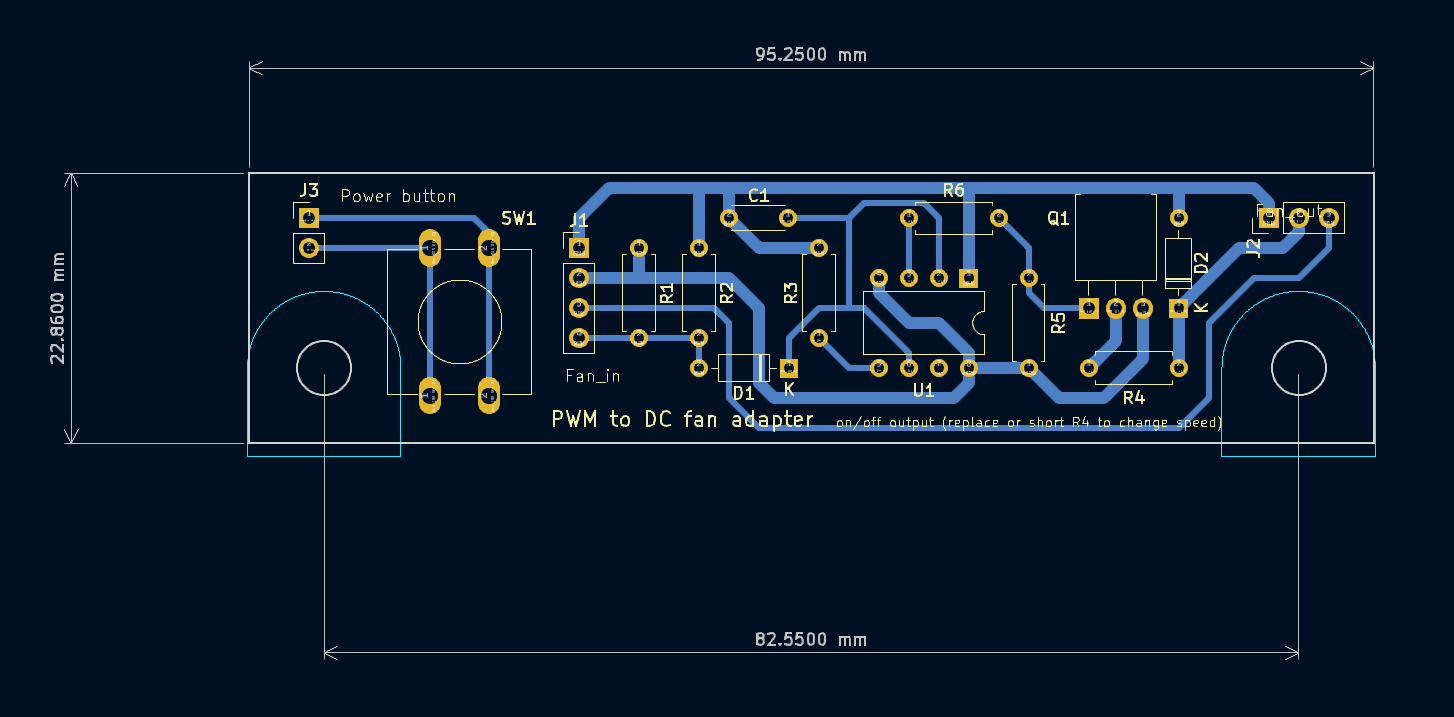
The power button is just a button that can be connected to the power pins of the motherboard to turn a computer on or off. This is not really related to the fan control, but I needed a button, so here it is.